DPSI Micro DualBat
Contents
Product description

Dual power supply with magnetic switch and regulated output voltage for 5/6cell NiCad/NiMH as well as LiIon/LiPo and LiFePo4 batteries. Regulated and stabilized output voltage 5.5V/5.9V or 5.9V/7.2V adjustable.
Dual electronically On/Off-switch for complete contact less switching operation with an external magnet from outside.
The used battery type and the low voltage detection can be programmed. Intelligent voltage monitoring with optical error indication.
Designed for 5 up to a max. of 10 servos. Supports 4A (@5.9V), 6A (@7.2V) permanent current and 25A peak current.
Features
| Feature | implemented |
|---|---|
| Electronic switch | Yes |
| Dual power supply | Yes |
| Voltage regulator | Yes |
| Servo current distribution | No |
| Servo signal distribution | No |
Versions
The versions of the DPSI Micro DualBat differ based on the selectable output voltage (5.5V / 5.9V or 5.9V / 7.2V) and the battery connector plug (JR or MPX).
- DPSI Micro DualBat 5.5V/5.9V JR
- DPSI Micro DualBat 5.5V/5.9V MPX
- DPSI Micro DualBat 5.9V/7.2V JR
- DPSI Micro DualBat 5.9V/7.2V MPX
Furthermore, there is a weight-reduced version that is designed for F3A scene and two versions with MPX sockets on the receiver side.
- DPSI Micro DualBat 5.9V/7.2V F3A Edition
- DPSI Mirco DualBat 5.5V/5.9V MPX-1xMPX
- DPSI Mirco DualBat 5.9V/7.2V MPX-1xMPX
- DPSI Mirco DualBat 5.5V/5.9V MPX-2xMPX
- DPSI Mirco DualBat 5.9V/7.2V MPX-2xMPX
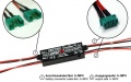
- DPSI-Micro-DualBat-5.5-5.9 JR Anschlüsse 640x400.jpg
JR battery connection
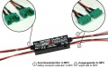
- DPSI-Micro-DualBat-5.5-5.9 MPX Anschlüsse 640x400.jpg
MPX battery connection
MPX battery connection, one MPX socket on receiver side
MPX battery connection, two MPX sockets on receiver side


Delivery contents
DPSI Micro DualBat, switching magnet with EMCOTEC tag, screws, screwing collar, drilling template, vibration protection, quick reference guide
Mounting suggestions
DPSI Micro Systems can be switched on and off contactless with an external magnet through the model's fuselage wall or with the transmitter, so they can be fixed at the fuselage inner sidewall. The switching on and off process with the magnet works up to a distance of about 8mm (0.3in) from the DPSI Micro's surface through the fuselage wall. To see the LED from the outside a small hole with 5mm (0.2in) diameter can be drilled in the fuselage wall.
Sticking on the DPSI Micro system
The DPSI Micro can be sticked on with silicone directly on the fuselage's inner sidewall.
Screwing on the DPSI Micro system
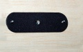
The DPSI Micro can be screwed from the outside to the fuselage wall. The required holes can be drilled using the included drilling template.
Both screws can be feed through the drilling holes from the outside. The screws are positioning helps for the self-adhesive foam rubber, which can be used as vibration protection. It is pushed over the screws from inside and glued to the fuselage's sidewall.
The DPSI Micro can be mounted with two included M3 screws. The screwing collars enlarge the area of support and inhibit in this way damage to the fuselage.
Foam rubber vibration protection
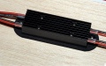
DPSI Micro on the fuselage's inner wall


Operating
Output voltage selection

The output voltage of the DPSI Micro can be selected in two steps: 5.5V / 5.9V or 5.9V / 7.2V. This can be done by selecting the desired voltage with the voltage selector.
Some servos are only approved for 4.8 volts according to their manufacturer's specifications (e.g. fast tail rotor servos for helicopters). Here, an output voltage of 5.5 volts is simply allowable. The manufacturer's values refer to 4-cell NiCad batteries. When fully charged, these batteries carry up to 5.5 volts, too. 4.8 volts are reached, when these batteries are almost discharged.
| Application | Recommended output voltage |
|---|---|
| Tail rotor servos, helicopters with quick gyros, servos for 4.8V according to manufacturer's specification | 5.5V |
| Gliders, small motorized models with up to approx. 5 servos | 5.5V oder 5.9V |
| Aerobatic models, jets, models with more than 5 servos | 5.9V |
| Competition models (motorized aerobatic flights) | 5.9V |
Switching on and off

For switching on the DPSI Micro the included magnet must be placed over the switching on position (ON) for approx. one second. The magnet can be placed in a distance up to 8 millimeters. After switching on the selected battery type is indicated by a blink code (see table 3: Blink codes/Battery types)
For switching off the DPSI Micro the magnet must be placed over the switching off position (OFF) for approx. two seconds. The distance can be also up to 8 millimeters.
The LED goes off and the receiver system is currentless.
Batteries
Battery types
As far as batteries are concerned, commercially available types are in use: NiCad, NiMH, Lithium-Ion (LiIon) and Lithium-Polymer (LiPo). Independent of the selected output voltage, these batteries are unlimited usable. Load capability should ranch from 3C up to 10C corresponding to the application.
Battery mounting
If the battery is placed in greater distance from the DPSI Micro due to the balance point reasons and so the connection cables are long, it is usefull to twist the wires. So better interference suppression is ensured.
DPSI Micro systems are not reverse polarity protected. Please be sure that the batteries are always connected correctly. The red pole must be connected to plus the black pole to minus.
Recommended battery capacities
In general, load capability and capacity of the batteries must be observed. As far as the selection of capacities is concerned, also consider, if you want to recharge the batteries between flights or if you want to operate the model all day long without recharging.
| Application | Recommended capacity |
|---|---|
| F3A models for competitions, small gliders with up to 5 servos | 2x 600mAh |
| Helicopters with fast tail rotor servos | 2x 1000mAh |
| Aerobatic models and small jets with up to 7 servos | 2x 1500mAh |
| Large gliders with up to 10 servos | 2x 2000mAh |
Battery programming
Because DPSI Micro uses intelligent voltage monitoring, the used battery type must be programmed once. The programmed type is stored in the micro controller of the DPSI Micro until eventually newly reprogrammed.
Starting programming mode variant 1
Programming starts when the DPSI is switched on while only one battery is connected (regardless of battery type and which battery is connected).
Starting programming mode variant 2
Programming starts when the voltage selector (see picture 1) is moved from one position to the other within 10 seconds of turning on.
Programming
As soon as programming mode starts, the LED is turned on for 3 seconds. Then a 3 second dark phase follows. This indicates "programming mode".
Now blinking codes for the specific battery type will be shown followed by 3 seconds break (see table 3). As soon as the desired type is indicated, the programming mode must be left within 3 seconds in advance of the next blink code. Programming mode is left by putting the sliding switch back to its previous position. The selected battery type is stored.
| Blink code | Battery type | Nominal voltage |
|---|---|---|
| 1x Blink | 5 NiCd/NiMH cells | 6.0 |
| 2x Blink | 6 NiCd/NiMH cells | 7.2V |
| 3x Blink | 2 LiIon cells | 7.2V |
| 4x Blink | 2 LiPo cells | 7.4V |
| 5x Blink | 2 LiFePO4 cells | 6.6V |
| 6x Blink | 7 NiCd/NiMH cells | 8.4V |
| 7x Blink | Deactivate tests / no error indication | --- |
If “7x blink” is selected (all tests disabled) the DPSI Micro does not monitor voltages. No empty batteries or other errors are indicated!
Error indication

The central LED indicates error types through blinking codes.
Battery failure
If a battery fails when used for a DPSI Micro, (e.g. cable broken or battery defective), the LED flashes continuously fast (5 Hz). This error type has highest priority. If the outage is removed during operation, the blinking still continues! So it can be determined after landing that the batteries or the connections should be checked.
Low voltage of battery
If the voltage of battery 1 drops below a certain value, this blinking code is output. The capacity of the battery usually suffices for one more flight before recharging is necessary. Nevertheless, the battery should be recharged anyway if this error code is displayed, assuming the correct battery type is programmed. This error code is repeated in a sequence of 6 seconds. If the error is qualified once, it stays active until turning the DPSI Micro off.
If both batteries of the DPSI Micro - DualBat indicate low voltage, both error codes are output alternatively.
Low voltage errors have lower priority than battery malfunction errors. Error output for battery malfunctions therefore is interrupted.
Specifications
| Power sources | 5 to 7 cell NiCd / NiMH batteries, 2 cell LiIon, LiPo, LiFePO4 batteries |
|---|---|
| Operating voltage | 4.8V ... 12V |
| Nominal voltage | 6.0V ... 8.4V |
| Output voltage | 5.5V or 5.9V respectively 5.9V or 7.2V (voltage selector) |
| Quiescent current (switched off) | <1µA per battery |
| Quiescent current (switched on) | approx. 90mA in total (LED on) |
| Max. permanent current @ 5.9V (15 minutes with LiPo batteries) | 4A |
| Max. permanent current @ 7.2V (10 minutes with LiPo batteries) | 6A |
| Max. peak current @ 5.9V (10 seconds with LiPo batteries) | 10A |
| Max. peak current (20ms) | 25A |
| Drop out losses @ 2A | 0.5V |
| CE test | according to 2004/108/EC |
| Environmental conditions | -10°C ... +50°C (14°F ... 122°F) |
| Permissable temperature range (Storage) | -25°C .... +85°C (77°F ... 185°F) |
| Dimensions | 73,4mm x 19,4mm x 14,1mm (2.9in x 0.76in x 0.55in) |
| Weight | approx. 28g (0.9oz) |
Dimensions (Dimension drawings)
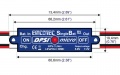
DPSI Micro top (example SingleBat)
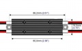
DPSI Micro bottom
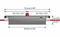
DPSI Micro side
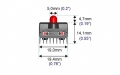
DPSI Micro front


Safety note
FAQs (Frequently Asked Questions)
Downloads
Latest Downloads
Download archive
- DPSI Micro SingleBat and DPSI Micro DualBat Operating instructions German
- DPSI Micro SingleBat and DPSI Micro DualBat Operating instructions English
- DPSI Micro SingleBat and DPSI Micro DualBat Operating instructions French