Difference between revisions of "SPS SafetyPowerSwitch"
(→Switching on and off of electrical motors) |
(→Specifications) |
||
| (6 intermediate revisions by the same user not shown) | |||
| Line 9: | Line 9: | ||
===Switching on and off of electrical motors=== | ===Switching on and off of electrical motors=== | ||
The SPS SafetyPowerSwitch serves for switching on and off of electic drives. When using the SPS SafetyPowerSwitch it is ensured that electic drives do not start accidentally and cause insuries e. g. during preparation of the model. The drive is supplied with voltage only when switch is operated consciously. | The SPS SafetyPowerSwitch serves for switching on and off of electic drives. When using the SPS SafetyPowerSwitch it is ensured that electic drives do not start accidentally and cause insuries e. g. during preparation of the model. The drive is supplied with voltage only when switch is operated consciously. | ||
| − | <div class="caution"> | + | <div class="caution">CAUTION: The SPS SafetyPowerSwitch serves only as protection against undesired starting of the electric drive. The switch must not be disconnected under load or used as an emergency stop switch.</div> |
===Anti flash protection=== | ===Anti flash protection=== | ||
| Line 21: | Line 21: | ||
* SPS SafetyPowerSwitch 70V 100/200A | * SPS SafetyPowerSwitch 70V 100/200A | ||
* SPS SafetyPowerSwitch 70V 140/280A | * SPS SafetyPowerSwitch 70V 140/280A | ||
| + | |||
| + | Find detailed specifications at [[#Specifications|Specifications]]. | ||
====Recent white label==== | ====Recent white label==== | ||
| Line 61: | Line 63: | ||
File:A72015 01.jpg|SPS XL SafetyPowerSwitch 180/360A | File:A72015 01.jpg|SPS XL SafetyPowerSwitch 180/360A | ||
</gallery> | </gallery> | ||
| + | |||
| + | ====Specifications former versions==== | ||
| + | {| class="wikitable" | ||
| + | |+align="bottom"|<!--''Table: Specifications former versions''--> | ||
| + | |- | ||
| + | !SPS SafetyPowerSwitch | ||
| + | !<span style="color: #cc6633;">34V 60/120A</span> | ||
| + | !<span style="color: #cc6633;">34V 60/120A (for Multicopters) | ||
| + | !<span style="color: #cc6633;">70V 60/120A</span> | ||
| + | !<span style="color: #cc6633;">70V 100/200A</span> | ||
| + | !<span style="color: #cc6633;">70V 140/280A</span> | ||
| + | !<span style="color: #cc6633;">60V 60/120A</span> | ||
| + | !<span style="color: #cc6633;">60V 120/240A</span> | ||
| + | !XL 180/360A | ||
| + | |- | ||
| + | |Suitable batteries (LiPo) | ||
| + | |2S ... 8S | ||
| + | |2S ... 8S | ||
| + | |6S ... 16S | ||
| + | |6S ... 16S | ||
| + | |6S ... 16S | ||
| + | |6S ... 14S | ||
| + | |6S ... 14S | ||
| + | |3S ... 16S | ||
| + | |- | ||
| + | |Voltage range | ||
| + | |6V ... 34V | ||
| + | |6V ... 34V | ||
| + | |18V ... 70V | ||
| + | |18V ... 70V | ||
| + | |18V ... 70V | ||
| + | |18V ... 60V | ||
| + | |18V ... 60V | ||
| + | |12V ... 70V | ||
| + | |- | ||
| + | |Current consumption (switched off) | ||
| + | |max. 0.5mA, typ. 0.25mA | ||
| + | |Information coming soon | ||
| + | |max. 0.5mA, typ. 0.25mA | ||
| + | |max. 0.5mA, typ. 0.25mA | ||
| + | |max. 0.5mA, typ. 0.25mA | ||
| + | | --- | ||
| + | | --- | ||
| + | | --- | ||
| + | |- | ||
| + | |Permanent current* | ||
| + | |60A | ||
| + | |100A | ||
| + | |60A | ||
| + | |100A | ||
| + | |140A | ||
| + | |60A | ||
| + | |120A | ||
| + | |180A | ||
| + | |- | ||
| + | |Maximum peak current** | ||
| + | |120A | ||
| + | |200A | ||
| + | |120A | ||
| + | |200A | ||
| + | |280A | ||
| + | |120A | ||
| + | |240A | ||
| + | |360A | ||
| + | |- | ||
| + | |Power dissipation @ 50A | ||
| + | |approx. 5W | ||
| + | |Information coming soon | ||
| + | |approx. 2.25W | ||
| + | |approx. 7.3W | ||
| + | |approx. 9.6W | ||
| + | | --- | ||
| + | | --- | ||
| + | | --- | ||
| + | |- | ||
| + | |Dimensions | ||
| + | |65 x 30 x 9.3mm | ||
| + | |65 x 30 x 9.3mm | ||
| + | |65 x 30 x 9.3mm | ||
| + | |65 x 30 x 16mm | ||
| + | |65 x 30 x 20mm | ||
| + | |65 x 30 x 9.3mm | ||
| + | |65 x 30 x 16mm | ||
| + | |82.4 x 62.4 x 26.5mm | ||
| + | |- | ||
| + | |Weight | ||
| + | |45g | ||
| + | |45g | ||
| + | |45g | ||
| + | |71g | ||
| + | |105g | ||
| + | |45g | ||
| + | |71g | ||
| + | |195g | ||
| + | |} | ||
| + | <div class="info">The listed <span style="color: #cc6633; font-weight: bold;">34 and 60 volt versions</span> of the SPS SafetyPowerSwitch are not longer available.</div> | ||
| + | <div class="hint">Hint: The mentioned <strong>*permanent current</strong> is calculated for the duration of a common flight, approx. <strong>up to 15 minutes.</strong> The <strong>**peak current</strong> is only permissible for a short period of <strong>up to three seconds.</strong></div> | ||
==Delivery contents== | ==Delivery contents== | ||
| Line 111: | Line 210: | ||
|- | |- | ||
!SPS SafetyPowerSwitch | !SPS SafetyPowerSwitch | ||
| − | |||
| − | |||
!70V 60/120A | !70V 60/120A | ||
!70V 100/200A | !70V 100/200A | ||
!70V 140/280A | !70V 140/280A | ||
| − | |||
| − | |||
| − | |||
|- | |- | ||
|Suitable batteries (LiPo) | |Suitable batteries (LiPo) | ||
| − | |2S ... | + | |2S ... 16S |
| − | |2S | + | |2S ... 16S |
| − | + | |2S ... 16S | |
| − | | | ||
| − | |||
| − | |||
| − | |||
| − | |||
|- | |- | ||
|Voltage range | |Voltage range | ||
| − | |6V ... | + | |6V ... 70V |
| − | |6V | + | |6V ... 70V |
| − | + | |6V ... 70V | |
| − | | | ||
| − | |||
| − | |||
| − | |||
| − | |||
|- | |- | ||
|Current consumption (switched off) | |Current consumption (switched off) | ||
|max. 0.5mA, typ. 0.25mA | |max. 0.5mA, typ. 0.25mA | ||
| − | |||
|max. 0.5mA, typ. 0.25mA | |max. 0.5mA, typ. 0.25mA | ||
|max. 0.5mA, typ. 0.25mA | |max. 0.5mA, typ. 0.25mA | ||
| − | |||
| − | |||
| − | |||
| − | |||
|- | |- | ||
|Permanent current* | |Permanent current* | ||
| − | |||
| − | |||
|60A | |60A | ||
|100A | |100A | ||
|140A | |140A | ||
| − | |||
| − | |||
| − | |||
|- | |- | ||
|Maximum peak current** | |Maximum peak current** | ||
| − | |||
| − | |||
|120A | |120A | ||
|200A | |200A | ||
|280A | |280A | ||
| − | |||
| − | |||
| − | |||
|- | |- | ||
|Power dissipation @ 50A | |Power dissipation @ 50A | ||
| − | |||
| − | |||
|approx. 2.25W | |approx. 2.25W | ||
|approx. 7.3W | |approx. 7.3W | ||
|approx. 9.6W | |approx. 9.6W | ||
| − | |||
| − | |||
| − | |||
|- | |- | ||
|Dimensions | |Dimensions | ||
| − | |||
| − | |||
|65 x 30 x 9.3mm | |65 x 30 x 9.3mm | ||
|65 x 30 x 16mm | |65 x 30 x 16mm | ||
|65 x 30 x 20mm | |65 x 30 x 20mm | ||
| − | |||
| − | |||
| − | |||
|- | |- | ||
|Weight | |Weight | ||
| − | |||
| − | |||
|45g | |45g | ||
|71g | |71g | ||
|105g | |105g | ||
| − | |||
| − | |||
| − | |||
|} | |} | ||
| − | |||
<div class="hint">Hint: The mentioned <strong>*permanent current</strong> is calculated for the duration of a common flight, approx. <strong>up to 15 minutes.</strong> The <strong>**peak current</strong> is only permissible for a short period of <strong>up to three seconds.</strong></div> | <div class="hint">Hint: The mentioned <strong>*permanent current</strong> is calculated for the duration of a common flight, approx. <strong>up to 15 minutes.</strong> The <strong>**peak current</strong> is only permissible for a short period of <strong>up to three seconds.</strong></div> | ||
Revision as of 15:51, 6 February 2019
Contents
Product description

The SPS SafetyPowerSwitch is a electronic safety switch for electric drives. An anti-flash-circuitry prevents the sparks during connecting the battery. The SPS SafetyPowerSwitch separates the motor from the battery. The electric motor drive remains inactive and therefore non hazardous until activation.
Key features
Switching on and off of electrical motors
The SPS SafetyPowerSwitch serves for switching on and off of electic drives. When using the SPS SafetyPowerSwitch it is ensured that electic drives do not start accidentally and cause insuries e. g. during preparation of the model. The drive is supplied with voltage only when switch is operated consciously.
Anti flash protection
Furthermore the SPS SafetyPowerSwitch prevents the flash occuring when connecting the battery.
Versions
Recent versions
The versions of the SPS SafetyPowerSwitch differ from the permissible permanent and peak current.
- SPS SafetyPowerSwitch 70V 60/120A
- SPS SafetyPowerSwitch 70V 100/200A
- SPS SafetyPowerSwitch 70V 140/280A
Find detailed specifications at Specifications.
Recent white label
In the year 2016 the native housing labels of the SPS SafetyPowerSwitches will be replaced with the new white labels.
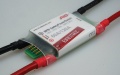
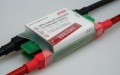
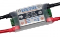
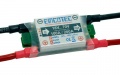
SPS SafetyPowerSwitch 70V 60/120A
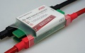
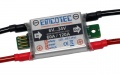
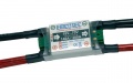
SPS SafetyPowerSwitch 70V 100/200A
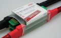
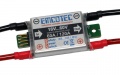
SPS SafetyPowerSwitch 70V 140/280A


Former versions
Here listed not longer available 34 and 60 volt versions of the SPS SafetyPowerSwitch were replaced by the 70 volt versions listed above.
- SPS SafetyPowerSwitch 34V 60/120A
- SPS SafetyPowerSwitch for Multicopter systems 34V 100/200A
- SPS SafetyPowerSwitch 60V 60/120A
- SPS SafetyPowerSwitch 60V 120/240A
White label
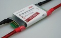
SPS SafetyPowerSwitch 34V 60/120A
SPS SafetyPowerSwitch for Multicopter systems 34V 100/200A


Silver label
The SPS SafetyPowerSwitches with the native white labels will be sold out gradually. In future only the new white labels will be available.
SPS SafetyPowerSwitch 34V 60/120A

SPS SafetyPowerSwitch 70V 60/120A
SPS SafetyPowerSwitch 60V 60/120A
SPS SafetyPowerSwitch 60V 120/240A
SPS SafetyPowerSwitch 70V 100/200A
SPS SafetyPowerSwitch 70V 140/280A


SPS SafetyPowerSwitch XL
Furthermore there was a SPS SafetyPowerSwitch in a larger design.
- SPS XL SafetyPowerSwitch 180/360A
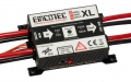
SPS XL SafetyPowerSwitch 180/360A

Specifications former versions
| SPS SafetyPowerSwitch | 34V 60/120A | 34V 60/120A (for Multicopters) | 70V 60/120A | 70V 100/200A | 70V 140/280A | 60V 60/120A | 60V 120/240A | XL 180/360A |
|---|---|---|---|---|---|---|---|---|
| Suitable batteries (LiPo) | 2S ... 8S | 2S ... 8S | 6S ... 16S | 6S ... 16S | 6S ... 16S | 6S ... 14S | 6S ... 14S | 3S ... 16S |
| Voltage range | 6V ... 34V | 6V ... 34V | 18V ... 70V | 18V ... 70V | 18V ... 70V | 18V ... 60V | 18V ... 60V | 12V ... 70V |
| Current consumption (switched off) | max. 0.5mA, typ. 0.25mA | Information coming soon | max. 0.5mA, typ. 0.25mA | max. 0.5mA, typ. 0.25mA | max. 0.5mA, typ. 0.25mA | --- | --- | --- |
| Permanent current* | 60A | 100A | 60A | 100A | 140A | 60A | 120A | 180A |
| Maximum peak current** | 120A | 200A | 120A | 200A | 280A | 120A | 240A | 360A |
| Power dissipation @ 50A | approx. 5W | Information coming soon | approx. 2.25W | approx. 7.3W | approx. 9.6W | --- | --- | --- |
| Dimensions | 65 x 30 x 9.3mm | 65 x 30 x 9.3mm | 65 x 30 x 9.3mm | 65 x 30 x 16mm | 65 x 30 x 20mm | 65 x 30 x 9.3mm | 65 x 30 x 16mm | 82.4 x 62.4 x 26.5mm |
| Weight | 45g | 45g | 45g | 71g | 105g | 45g | 71g | 195g |
Delivery contents
SPS SafetyPowerSwitch, desired switch actuator, screws, operating instruction
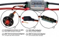
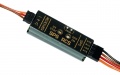
Mounting
The SPS SafetyPowerSwitch is looped in between the drive battery and the motor controller. Therefor e. g. 4mm gold plated plugs or sockets must be applied on the input side. The red cable of the SPS is the positive pole, the black one the negative pole. Obeying polarity is mandatory. The output of the SPS SafetyPowerSwitch must be connected to the motor controller according to polarity. The total cable length between motor controller and battery (incl. SPS SafetyPowerSwitch) should be as short as possible. The SPS SafetyPowerSwitch's PCB can be fixed with Velcro tape to an appropriate surface. Alternatively the fixing with a small screw is possible. For using this method there is a small drilling hole at the end of the PCB. Please observe not to shorten the small solderpads beside the hole with the used srew.
Switching on and off
The SPS SafetyPowerSwitch can be switched on and off by using the connected switch actuator. After switching on the SPS SafetyPowerSwitch the status LED of the switch actuator starts shining.
The SPS SafetyPowerSwitch can only be switched on and off by an external switch actuator. Switching on and off of the SPS SafetyPowerSwitch at the housing itself is not possible. One of three available SPS switch actuators is contained within delivery contents.
SPS switch actuators
For the SPS SafetyPowerSwitch three SPS switch actuators are available:
- SPS Gas cap switch actuator
- SPS Pin switch actuator
- SPS Remote switch acutator
All SPS switch actuators must be connected on the SPS switch actuator connector at the "IN" side of the SPS SafetyPowerSwitch.
Übersicht SPS-Schaltgeber
SPS Gas cap switch actuator with plugged magnet
SPS Gas cap switch actuator without magnet
SPS Pin switch actuator with plugged pin

SPS Pin switch actuator without pin
SPS Remote switch actuator


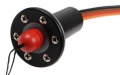
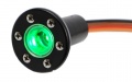
SPS Gas cap switch actuator

Switching on and off with the SPS Gas cap switch actuator happens with an external magnet which is plugged inside the SPS Gas cap switch actuator's funnel-shaped opening in idle-mode (SPS SafetyPowerSwitch switched off). When magnet pulled out of the opening the SPS SafetyPowerSwitch is switched on. A green LED inside the SPS Gas cap switch actuator's opening indicates the activated system. For deactivating the SPS SafetyPowerSwitch and the complete system the external magnet must be plugged into the opening of the SPS Gas cap switch actuator again.
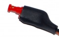
SPS Pin switch actuator

Switching on and off with the SPS Pin switch actuator happens with an external pin which is plugged inside the SPS Pin switch actuator's opening in idle-mode (SPS SafetyPowerSwitch switched off). When pin is pulled out of the opening the SPS SafetyPowerSwitch is switched on. A green LED inside the SPS Pin switch actuator's opening indicates the activated system. For deactivating the SPS SafetyPowerSwitch and the complete system the external pin must be plugged into the opening of the SPS Pin switch actuator again.
SPS Remote switch actuator

Main article: SPS Remote switch actuator
Switching on and off with the SPS Remote switch actuator happens with an defined receiver channel. Therefor the desired switching points on the transmitter must be programmed. Optionally the SPS Remote switch actuator can be operated additionally with the SPS Pin switch actuator or the SPS Gas cap switch actuator. See details of programming and important hints inside Main article.
Specifications
| SPS SafetyPowerSwitch | 70V 60/120A | 70V 100/200A | 70V 140/280A |
|---|---|---|---|
| Suitable batteries (LiPo) | 2S ... 16S | 2S ... 16S | 2S ... 16S |
| Voltage range | 6V ... 70V | 6V ... 70V | 6V ... 70V |
| Current consumption (switched off) | max. 0.5mA, typ. 0.25mA | max. 0.5mA, typ. 0.25mA | max. 0.5mA, typ. 0.25mA |
| Permanent current* | 60A | 100A | 140A |
| Maximum peak current** | 120A | 200A | 280A |
| Power dissipation @ 50A | approx. 2.25W | approx. 7.3W | approx. 9.6W |
| Dimensions | 65 x 30 x 9.3mm | 65 x 30 x 16mm | 65 x 30 x 20mm |
| Weight | 45g | 71g | 105g |
Optional extensions
Usage of SPS Support capacitor

During switching-on process motor controllers may need more current than during regular operation. In this case a short period high current flow could cause a voltage drop at the motor controller and lead to malfunctions. Such voltage drop can also be caused by high-resistance long cables between the drive battery and the motor controller. This voltage drops at the motor controller can be prevented by soldering a capacitor between SPS SafetyPowerSwitch and motor controller. The SPS Support capacitor provides the current peaks required by the motor controller and unloads the drive battery by decreasing the current flow from the drive battery. So the voltage drop at the motor controller is reduced. The total cable length which is recommended without a capacitor can be seen inside your motor controller's operating manual
Specifications SPS Support capacitor
| Entity | Value |
|---|---|
| Max. voltage | 63V |
| Capacity | 2200µF |

Using a power resistor for pre-charging capacitors

Motor controllers have capacitors which provide short current peaks required during the switchin-on process. This capacitors are being charged when the motor controller is switched on, so depending on the capacitor's input capacity a increased current flow may occur. If the total capacity of all capacitors increases 1500µF occuring currents may damage the SPS SafetyPowerSwitch. This can be prevented when capacitors are pre-charged with a lower current before the SPS SafetyPowerSwitch is switched on. Therefor the minus pole can be bypassed with an external power resistor. The power resistor can be soldered directly between minus pole input and minus pole output. If desired it can be switched with a pushbutton.
Power resistor without pushbutton

The power resistor can be soldered directly between minus pole input and minus pole output. The motor controller's capacitors will be charged when the battery is plugged. When capacitors are fully charged the SPS SafetyPowerSwitch's LEDs as well as the LEDs of the connected SPS switch actuator are illuminated. This happens a few seconds after plugging the battery. The SPS SafetyPowerSwitch can now be safely switched on because the motor controller's capacitors are pre-charged, no high current flows can occur.
Power resistor with pushbutton

The power resistor can be soldered directly between minus pole input and minus pole output. A pushbutton can be implemented to make the bridge switchabel. The motor controller's capacitors will be charged when the battery is plugged and the pushbutten is pushed for a few seconds. When capacitors are fully charged the SPS SafetyPowerSwitch's LEDs as well as the LEDs of the connected SPS switch actuator are illuminated. The SPS SafetyPowerSwitch can now be safely switched on because the motor controller's capacitors are pre-charged, no high current flows can occur.
Constraints
The SPS SafetyPowerSwitch cannot be used in combination with the following Graupner/SJ products:
- Electric Air Module2-14S, Vario HoTT
- General Engine-Module 2-6S Gr. HoTT
- General Air-Module 2-6S, Vario Gr. HoTT
- Voltage Module 2-4S, EH
- Voltage Module 2-4S, XH
Proved motor controller
So far the following motor controllers were tested with the SPS SafetyPowerSwitch:
- Hacker MasterMezon series
- Hacker MasterSPIN Pro series
- Hacker MasterBasic series
- Kontronik JIVE series
Downloads
Latest Downloads
- Quick reference guide Version 2.0 February 2019
Download archive
- Quick reference guide Version 1.0 October 2018